In the realm of electronic tinkering, the MAX7219 dot matrix displays have emerged as a canvas for enthusiasts to express their creativity. These displays, characterized by their grid-like structures, offer a unique platform for dynamic and customizable visual communication. Their versatility and ease of programming have made them a popular choice among hobbyists and professionals alike.
The significance of dot matrix displays in DIY projects is undeniable, particularly when considering their wide range of applications. Initially, you can use these displays to craft a simple message board. Furthermore, they are capable of creating a miniature billboard, illustrating their versatility. Consequently, dot matrix displays have revolutionized the way we interact with electronic devices. Not only are they versatile, but their ease of use has also made them a favorite among makers and creators.
The global LED display market reached a value of $6.3 billion in 2021, and analysts predict it will grow at a compound annual growth rate (CAGR) of 8.4% from 2022 to 2028, highlighting their increasing popularity.
To begin with, let’s demystify the process of integrating dot matrix displays with the MAX7219 LED Matrix chip and Arduino Uno. Subsequently, we will explore the intricacies involved in setting up, programming, and fine-tuning your display. Using this method, you can effortlessly and accurately craft visually impressive projects.
This guide aims to elevate your understanding and mastery over dot matrix displays, whether you are a seasoned maker or a curious beginner.
Significance of Dot Matrix Displays in DIY Projects
Dot matrix displays, the unsung heroes of countless DIY (do it yourself) projects, mesmerize and inform with their arrays of LEDs. Furthermore, you have likely encountered them in various settings. Train stations, for instance, often display departure times. Additionally, these displays are prominent on roadside billboards and, notably, in the iconic Times Square in New York City.

But what makes them truly special is their versatility in DIY projects. Imagine creating your digital message board, a real-time weather display, an eye-catching game scoreboard, or an animated holiday decoration.
The ability to showcase dynamic information through bright, attention-grabbing visuals renders these displays indispensable in contemporary electronic projects. Moreover, the possibilities are virtually endless, only limited by your creativity. Consequently, dot matrix displays have the power to transform your ideas into a visually stunning reality.
Dot Matrix Displays – Understanding the Basics
Before diving deep into the integration of dot matrix displays with the MAX7219 and Arduino, it’s essential to grasp the foundational knowledge. Let’s get a clear understanding of what a dot matrix display is, its structure, and the myriad applications it serves in the world of electronics.
What is a Dot Matrix Display?
A dot matrix display, abbreviated as DMD, is a two-dimensional array of light-emitting diodes (LEDs0 arranged in rows and columns. When viewed from a distance, these LEDs, or ‘dots,’ combine to form characters, symbols, and other graphics.

The beauty of a dot matrix display lies in its simplicity and versatility. By controlling which LEDs are turned on and off, one can display a wide range of patterns and information.
Structure of a Dot Matrix Display
An array of LEDs organized into rows and columns characterizes a typical dot matrix display. Importantly, you can individually manipulate each LED, often called a ‘pixel,’ within this grid to be either on or off. Consequently, by managing the state of these pixels, you can produce a wide range of visual displays. Additionally, the grid is available in various sizes, with the 8×8 configuration being particularly prevalent. This implies that there are eight rows and eight columns, summing up to 64 LEDs in a single matrix.
Typically, a rectangular or square module houses LEDs and often pairs them with a diffused lens to boost visibility. Furthermore, the allure of a dot matrix display stems from its straightforwardness and modular design. Additionally, you have the option to link several displays together, thereby creating a more expansive canvas suitable for complex designs and extended scrolling messages.
Applications of Dot Matrix Displays
The applications of dot matrix displays are vast and varied and as diverse as your imagination allows. Here are a few examples:

- Information Boards and Displays: Dot matrix displays are a staple of public information displays such as train schedules, flight information at airports, and electronic billboards, where they disseminate real-time information such as schedules, announcements, and alerts.
- Wearables and Fashion: Integrating dot matrix displays into clothing and accessories can lead to innovative fashion statements, such as LED-lit ties or dynamic messages displaying hats. Many digital clocks use dot matrix displays to showcase the time, date, and even temperatures.
- Advertisement Panels: Businesses utilize dot matrix displays to display dynamic advertisements, promotions, and messages to attract customers.
- Home Automation: DIY enthusiasts often use dot matrix displays in home automation projects to display time, weather, notifications, and more.
- Gaming and Gadgets: Classic arcade games and handheld devices have historically utilized dot matrix displays, effectively rendering everything from simple graphics to complex games and in-game information. These displays showcase not only basic graphics but also detailed in-game content.
- Entertainment, Art, and Decor: Artists, creators, and hobbyists use dot matrix displays as a canvas of experimentation, creating dynamic visual art, light shows, and stunning light installations. DIYers also use it to create personalized message boards, a mini-stock ticker, or even a music visualizer.
- Educational Tools: In educational kits and science projects, instructors use dot matrix displays to teach coding, electronics, data visualization, and digital art.
- Industrial Indicators: In industrial settings, companies use dot matrix displays to show status indicators, error messages, and process information.
Introduction to MAX7219
The MAX7219 LED Matrix is a compact integrated circuit that plays a crucial role in controlling dot matrix displays. Thanks to its serial input/output design and common-cathode configuration, this driver simplifies the interface between microprocessors and 7-segment numeric LED displays. Additionally, it enhances its versatility by enabling the control of LED matrices. Developed by Maxim Integrated, this chip is a favorite among electronic enthusiasts and professionals alike due to its ease of use and powerful capabilities.
Overview of MAX7219
The MAX7219 expertly connects microprocessors with various display types, including 7-segment numeric LED displays that can extend up to 8 digits, bar-graph displays, or 64 individual LEDs. Moreover, this versatility aligns perfectly with an 8×8 dot matrix display. Commonly referred to as a “serially interfaced, 8-digit LED display driver,” the MAX7219 LED Matrix has earned this title for its efficient functionality. Additionally, the device is housed in a compact 24-pin package and operates seamlessly on a 5V power supply.

To enhance the design efficiency, the design team specifically designed the chip to reduce the number of I/O pins required to operate the display. This approach not only simplifies the overall design but also frees up valuable resources on the microcontroller. Additionally, the MAX7219 LED Matrix acts as a crucial interface between your microcontroller, such as an Arduino, and the dot matrix display. Consequently, it significantly simplifies the process of controlling a multitude of LEDs, which, if managed directly, can be quite complex.
Functionalities of MAX7219
The MAX7219 comes packed with a host of features and functionalities that make it a preferred choice for controlling LED matrices:

- Ease of Control: MAX7219 LED Matrix allows you to control up to 64 individual LEDs with just three pins from a microcontroller.
- Multiplexing Support: The chip handles the multiplexing work, meaning it can control all the LEDs in a matrix even though they’re not all ON at the same time. It also ensures that the display is refreshed at a visually stable rate, reducing the microcontroller’s workload and ensuring smooth operation.
- Brightness Control: The MAX7219 allows you to adjust the intensity of the LEDs, providing flexibility in how your display appears to match your specific applications.
- Daisy-Chaining/Cascading Capability: One of the key advantages of the MAX7219 LED Matrix is its daisy-chaining capability. This feature allows for connecting multiple MAX7219 chips in series, enabling the control of several dot matrix displays. Consequently, you can manage numerous displays using a single set of data, clock, and load pins from your microcontroller, simplifying the design and reducing the complexity of your setup.
- Built-in Decoding: The chip includes a BCD (Binary Coded Decimal) decoder that simplifies the process of displaying numbers on 7-segment displays.
- Power Saving Mode: The MAX7219 LED Matrix includes a shutdown mode that powers down the system but retains all data in its registers, allowing for efficient power management.
- Serial Data Input/Output: The MAX7219 LED Matrix interfaces with your microcontroller through a serial data interface. Initially, it receives data in a serial format. Subsequently, this data is converted into the appropriate LED states, thereby simplifying the communication process.
- Integrated Display RAM: The chip also incorporates an integrated 8×8 status RAM to store the data to be displayed, simplifying the process of updating and refreshing the display.
Benefits of Controlling LED Matrices
The MAX7219’s incorporation into your project offers several advantages:

- Simplified Control: The chip simplifies the process of driving multiple LEDs with easy wiring and control logic while taking care of many low-level tasks, such as LED multiplexing and refreshing, making it easier to design and troubleshoot your projects.
- Scalability: The MAX7219 LED Matrix’s cascading capability allows you to expand as your project demands without significantly increasing complexity.
- Stability and Reliability: The MAX7219’s built-in functionalities ensure a stable and flicker-free display, enhancing the visual appeal of your projects.
- Resource Efficiency: By minimizing the number of pins required from the microcontroller, the MAX7219 LED Matrix allows for more complex and feature-rich projects.
- Enhanced Display Quality: The chip’s brightness control guarantees the visibility of your display in various lighting conditions. Additionally, the integrated RAM simplifies the manipulation and updating of the displayed content.
Gathering the Essentials
To become proficient in working with dot matrix displays using MAX7219 and Arduino, it’s crucial to assemble a set of key components and tools. Let’s explore the essential items required to realize your creative ideas.
Components Required
Here’s a comprehensive list of components you need to ensure you have everything at your fingertips to ensure a smooth and successful project:
- Arduino Board: This is the brain of your project. It will control the dot matrix display via the MAX7219 chip.
Type: Arduino Uno, Arduino Nano, or any other compatible board.
Specifications: You should have at least three available digital I/O pins.
- MAX7219 Display Driver: This is the heart of your display control. Depending on the size of your display, ensure you have one or more MAX7219 chips.
Type: LED display driver IC.
Specifications: Suitable for driving a common cathode 8×8 LED matrix.
- Dot Matrix Display: The star of the show is selecting the appropriate size and type of display that aligns with your project’s specific needs. Firstly, standard sizes such as the 8×8 display are commonly available. Additionally, for larger requirements, the 16×16 display option is also offered.
Type: 8×8 LED Matrix
Specification: Common cathode or anode configuration, chosen based on availability and personal preference.

- Jumper Wires: These will be your electrical connections.
Type: A mix of male-to-male jumper wires, male-to-female jumper wires, and female-to-female jumper wires.
Quantity: A sufficient number to make all necessary connections.
- Breadboard or Custom PCB: A breadboard can be helpful for prototyping and testing connections before soldering. For a more permanent solution, you can also design a custom PCB (printed circuit board).
- Breadboard Type: Standard, solderless
Purpose: Facilitate easy connections and modifications during prototyping.
- Power Supply: Depending on your display size and brightness requirements, you may need an external power supply to ensure stable operation.
Type: 5V power supply compatible with your Arduino board.
Specifications: Ensure it meets the power requirements of your setup.
- Resistors and Capacitors:
Type: This may be required to adjust brightness or stabilize the power supply.
Specifications: Values may vary based on project needs.
- Soldering Kit: If you are connecting components that don’t have pre-fitted components (or a custom PCB), you may need to put solder wires in place.
Components: Soldering iron, soldering wire, and flux.
Purpose: For permanent connections or if and as required.
- USB Cable: This is for programming your Arduino board and powering it during the development phase.
- Computer: To run the Arduino IDE and upload your code to the Arduino board.
- Headers (optional): Headers can make it easier to connect the MAX7219 and Arduino to your breadboard or custom circuit.
Tools and Software
Once you have your components ready, you’ll need to set up your software environment and gather a few tools:

- Arduino IDE: This integrated development environment is crucial for programming your Arduino board. It is free and open-source and supports a wide range of Arduino-compatible boards.
- MAX7219 Libraries: To simplify the process of controlling the MAX7219 chip, you’ll first need to install the MAX7219 library in the Arduino IDE. This library offers pre-written functions and methods that are essential for controlling the dot matrix displays. Moreover, it can be conveniently installed directly from the Arduino IDE using the library manager.
- Wire Strippers and Cutters: These tools are helpful for preparing and cutting wires to facilitate easy and clean connections.
- Multimeter: It is helpful in troubleshooting and verifying voltages, currents, and continuity in your circuit.
- Screwdriver: This is in case you need to make adjustments or secure components.
- Schematic Design Software: If you plan to create a custom PCB, software like Fritzing, Eagle, or KiCad can help you design your circuit layout.
- Soldering Station: If you’re working with a custom PCB, a soldering station with a fine tip will be necessary for secure connections.
- Device Drivers: If you are using a Windows-based computer, ensure that the necessary drivers are installed for the Arduino board.
Having every required component and tool at hand is crucial for ensuring a smooth and enjoyable project experience. Additionally, with all the elements in place, we’re set to eagerly dive into the exciting world of connections and coding!
Diving Into the Connections: Circuit Diagram to Connect Max7219
To create a successful dot matrix display project, it’s essential to focus on the connections between the Arduino, MAX7219, and the dot matrix displays. Therefore, here’s a detailed, step-by-step guide to assembling the circuit:
- MAX7219 to Dot Matrix Displays: The dot matrix display will have multiple pins, usually labeled as rows and columns for an 8×8 matrix. In general, you’ll need to connect the DIG0-DIG7 pins of the MAX7219 to the corresponding rows of the 8×8 dot matrix displays. Similarly, connect the SEGA-SEGG and DP pins of the MAX7219 to the corresponding columns of the dot matrix displays. Ideally, consult the datasheet for accurate pin connections. Specifically, it will detail the exact mapping of each matrix pin to the corresponding pin in the MAX7219 LED Matrix.
- Power Supply: Connect the VCC pin and GND pin of the MAX7219 to the 5V pin and GND pin on the Arduino, respectively.
- Arduino and MAX7219 Data Connections: Connect the DIN (DATA IN) pin on the MAX7219 LED Matrix to the D11 Pin on the Arduino (or any other digital pin you prefer).
- Connect the MAX7219’s CS (Chip Select) pin to the Arduino’s D10 (or any other digital pin).
- Connect the MAX7219 LED Matrix’s CLK (clock) pin to the Arduino’s D13 pin (or any other digital pin).
- Additional Components:
- Connect a 10kΩ resistor between the MAX7219’s ISET pin and GND. This will set the current for the LEDs.
- Connect a 10µF capacitor between VCC and GND close to the MAX7219 LED Matrix to stabilize the power supply.
- Optionally, add a 0.1µF capacitor between the VCC and GND for additional noise suppression.

Understanding Connections in Depth
Let’s walk through the steps to ensure you connect your dot matrix displays, MAX7219, and Arduino seamlessly.
STEP-I: Understanding the PinOut
MAX7219 Pin Out:
- VCC – This is the power supply pin. It typically operates at 5V.
- GND – Ground Pin
- DIN (Data IN) – This pin receives data from the Arduino.
- CS (Chip Select/Latch): This pin turns the chip on or off. When low, the chip is active.
- CLK (Clock) – This pin receives the clock pulses, which dictate the rate at which data is sent to the MAX7219 LED Matrix.
- DOUT (Data Out) – This pin sends data out, which is useful when daisy-chaining multiple MAX7219 chips.
- ISET (Current Set) – This pin is connected to a resistor to set the LED current.
- DIG0-DIG7 – Digit drive Pins connected to the rows of the dot matrix display.
- SEGA-SEGG – Segment Drive Pins are connected to the columns of the dot matrix displays.
Dot Matrix Displays Pin Out:
- VCC – Power Supply Pin (5V)
- GND – Ground Pin
- DIN – Data In, connected to DIN on MAX7219
- CS – Chip Select, connected to CS on MAX7219
- CLK – The clock is connected to CLK on MAX7219.
STEP-II: Wiring The Components
With the pinout understood, let’s proceed to connect the components.
- Power Connections:
- Connect the VCC Pin of the MAX7219 to the 5V Pin on the Arduino.
- Connect the GND pin on the MAX7219 to the GND pin on the Arduino.
- Data Connections:
- Connect the DIN pin of the MAX7219 to the D11 pin on the Arduino (or any other digital pin of your choice)
- Connect the CS pin on the MAX7219 to the D10 pin on the Arduino (or another digital pin)
- Connect the CLK pin of the MAX7219 to the D13 pin on the Arduino (or another digital pin)
- Dot Matrix Display to MAX7219
- Connect the VCC, GND, DIN, CS, and CLK pins of the dot matrix display to the corresponding pins on the MAX7219 LED Matrix.
- Additional Components
- Connect a 10µF capacitor between VCC and GND on the MAX7219.
- Connect a 10kΩ resistor to the ISET pin on the MAX7219.

STEP-III: Powering the Setup
Ensuring that your setup is powered correctly is crucial to avoid any damage to the components.
- Power Source: To ensure optimal performance, verify that your power supply can deliver 5V and sufficient current for your setup. Keep in mind that the current requirement may rise when you are daisy-chaining multiple displays. An 8×8 matrix can draw up to 500mA when all the LEDs are ON. While the Arduino can be powered via USB during development, for standalone projects, consider using a 5V battery or adapter.
- Check Connections: Before powering up, double-check all connections to ensure there are no short circuits or misconnections.
- Gradual Power-Up: Initially, power up the Arduino via USB to ensure that the connections are correct. Once verified, you can switch to your dedicated power supply. If using an adapter, ensure it’s plugged into a surge-protected outlet.
- Monitor the Display: Initially, the dot matrix display might only show something once you upload the program. However, ensure there’s no flickering or unusual brightness, as these could indicate issues.
- Safety First: Never make or alter connections while the system is powered ON. Always turn off the power, make your changes, and then power back ON.

Meticulously follow these steps to set a strong foundation for your dot matrix display project, ensuring that you correctly set the hardware and get it ready for programming.
Coding and Programming – Setting Up the Environment
Once your hardware is connected and ready, the next step is to set up the software environment. It involves configuring the Arduino IDE and installing the necessary libraries to control the dot matrix display using the MAX7219 chip.
Installing the Arduino IDE
The Arduino Integrated Development Environment (IDE) is the primary tool you’ll use to write, compile, and upload code to your Arduino board.

- Download: Visit the official Arduino website (https://www.arduino.cc/en/software) and download the latest version of the Arduino IDE suitable for your operating system. (Windows/MacOS/Linux)
- Installation: Run the downloaded installer and follow the on-screen instructions to install the Arduino on your computer.
- Configure the IDE: Once installed, open the Arduino IDE and:
Go to “Tools>>Board” and select the type of Arduino board you are using (for example, Arduino UNO). - Select the Port: Go to “Tools>>Port” and select the port to which your Arduino is connected. It usually appears as “COMxx” on Windows and “dw/#yUSBx” or /dw/#yACMx” on Linux or MacOS.
Setting Up The Arduino IDE
Once the Arduino IDE is installed, you’ll need to configure it for your specific Arduino board.
- Board Selection: Open the Arduino IDE, navigate to “Tools>>Board,” and select the type of Arduino board you are using, such as an Arduino Nano or UNO.
- Port Selection: Connect your Arduino board to your computer using a USB A to B cable. Then, in the Arduino IDE, go to “Tools>>Port” and select the COM port to which your Arduino is connected. It should be labeled with the Arduino board’s name.

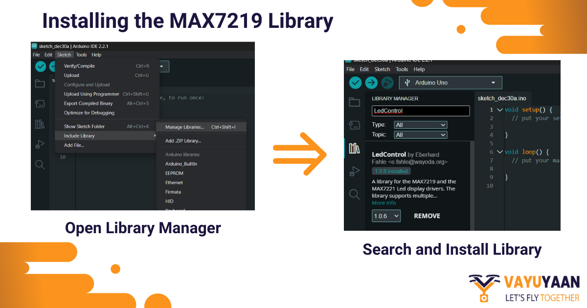
Installing the MAX7219 Library
The MAX7219 library provides pre-written functions that make it easy to control the dot matrix display.
- Open Library Manager: In the Arduino IDE, navigate to “Sketch>>Include Library>> Manage Libraries.” It will open the Library Manager.
- Search and Install: In the Library Manager’s search bar, enter “MAX7219” or “LedControl.” Subsequently, you’ll notice a range of libraries associated with the MAX7219 LED Matrix. Specifically, the LedControl is among the most popular and extensively utilized libraries. Click on it and then click the “Install” button.
- Include the Sketch: Once installed, you can include the library in your code by navigating to “Sketch>>Include Library” and selecting “LedControl” or whichever library you installed.
- Verify Installation: Once installed, you can check if the library is correctly added by navigating to “Sketch>>Include Library.” You should see the “LedControl” library listed in the list of available libraries.
With the Arduino IDE setup and the necessary library installed, you’re now ready to start coding and bringing your dot matrix display project to life.
Testing the Setup
Before proceeding, it’s good practice to ensure that your setup is working correctly.
- Load Sample Sketch: To open a sample sketch in the Arduino IDE, first navigate to File > Examples > LedControl > LCDDemo. This particular sketch, primarily designed for testing the MAX7219, will effectively display a series of patterns on your dot matrix display.
- Upload the Sketch:
- Connect your Arduino board to the computer using a USB cable.
- Click on the “Upload” button (right arrow icon) in the Arduino IDE to compile and upload the sketch to your Arduino board.
- Verify the Output: Once the sketch is uploaded, you should see patterns displayed on your dot matrix display, confirming that your environment setup is correct.

By following these steps, you can ensure that your software environment is correctly configured and ready for you to start coding your dot matrix project.
Understanding the Code
Once you set up the environment, you can delve into the code that will bring your dot matrix display to life. By understanding the structure and intricacies of the Arduino code, you’ll be better equipped to customize and expand upon your dot matrix display projects.
Code Structure
Arduino code, commonly known as “Sketch,” is crafted in C/C++ and is meticulously structured to guarantee seamless execution on the Arduino board. Furthermore, it is typically divided into four primary sections:
- Declarations and Variables: At the beginning of the sketch, you’ll typically find the library inclusions using the #include derivative. For our dot matrix display project, you might see “#include<LedControl.h>.
- Following this, the global variables and constants are declared. For instance, you might declare pins connected to the MAX7219 LED Matrix or the number of devices being used.
PROGRAM:
LedControl for Dot Matrix Display
#1 By creating an object
“cpp
#include” LedControl.h”//include the LedControl Library
LedControl lc = LedControl (12,11,10,1); //Create a new LedControl Object.
“
#2 by defining Pins for communication using directives
“cpp
#include” LedControl.h.”
#define DIN_PIN11
#define CS_PIN10
#define CLK_PIN13” - Setup() Function: The setup() function runs once when the Arduino is powered ON or reset. Here, you initialize the dot matrix display, set pin modes, and perhaps clear the display to start fresh.
“Cpp{
lc. shutdown (0, false); // wakeup the MAX7219
lc.setIntensity (0,8); // set brightness level (0 to 15)
lc.clearDisplay (0); // clear the display
Loop Function: The “loop()” function, which contains code executed repeatedly by the Arduino, serves as the core of your dot matrix display project. Here, you can seamlessly integrate code to display patterns, text, and animations.
“cpp
void loop (){
//your code to display patterns, text, numbers, or animation
}
“
- User-Defined Functions: To keep the code organized and modular, you might create user-defined functions. For example, a function named ‘displayText()’ might handle the logic for displaying text on the dot matrix display.
Displaying Text Characters and Numbers
To display text and numbers on the dot matrix display, you need to manipulate the LEDs in a pattern that represents each character. You can do so by using specific functions provided by the MAX7219 library. Here’s a breakdown of how this is typically achieved.
“cpp
LedControl lc = LedControl (DIN, CLK, CS, number of devices);
or
LedControl lc = LedControl (DIN_PIN, CLK_PIN, CS_PIN, 0);
Defining and Displaying Characters
To display characters, you will often use predefined byte patterns representing each character. For instance, the letter ‘A’ might be represented as a specific pattern of LEDs, all in the form of an array of bytes, where each byte represents a row of LEDs.
“cpp
byte A[8] = {0x00, 0x18, 0x24, 0x3C, 0x24, 0x024, 0x00};
“
The LedControl library provides functions to set rows and columns of LEDs according to a character. For example, to display character ‘H’:
In the loop() function, you can use the setChar() function:
“cpp
void loop (){
lc.setChar(0,0,’H’, false);//Display ‘H’ on the display
delay(1000);//wait for 1 second
lc.clearDisplay(0);//clear the display
//continue with other characters or numbers
}”
Displaying Numbers
Similar to characters, numbers are represented by specific LED patterns. The LedControl library also provides a built-in function, setDigit(), to display numbers, making this process straightforward. Here’s a simple example to display the number’ 5′.
“cpp
lc.setDigit(0,0,5,false);//display the number 5 on the first device, without leading zeroes
delay(1000); //wait for 1 second
lc.clearDisplay(0); //clear the display
//continue with other characters or numbers
}”
Customizing the Display
Enhancing your dot matrix displays with custom animations and patterns is an excellent strategy to make your project more distinctive. Firstly, by skillfully manipulating the LEDs, you can develop dynamic visual effects. Furthermore, these effects have the potential to captivate and engage your audience, adding an extra layer of appeal to your project.
To create custom animations, you can define patterns as byte arrays and then display them in sequence. Each byte represents a row, and each bit in the byte represents an LED in that row. Here is an example of heart animation:
“cpp
byte heart1[8]=
{B00100100,
B01011010,
B10000001,
B01000010,
B00100100,
B00011000,
B00000000};
byte heart2[8]=
{B00000000,
B00100100,
B01011010,
B10000001,
B01000010,
B00100100,
B00011000};
void loop(){
display Pattern(heart1);
delay(500);
display Pattern(heart2);
delay(500);
}
void display Pattern(byte pattern[]){
for (int i=0; i<8;i++){
lc.setRow(0,i,pattern[i]);
}
}”
In this example above, two heart patterns, ‘heart1’ and ‘heart2’, are defined and displayed in sequence, creating a pulsing heart animation.
Tips for Creating Custom Animation
- Plan Ahead: Sketch out your animation before diving into coding. This will give you a clear roadmap to follow.
- Start Simple: Begin with simple patterns and gradually add complexity.
- Optimize Delay: Adjust the delay between frames to make your animation smoother or slower based on your preference.
- Reuse Patterns: You can create modular patterns and reuse them in different animations.
- Use External Tools: There are online tools and software that can help you design animations for dot matrix displays and even generate code.
Scrolling Text and Adjusting Speed
Dot matrix displays are well-known for their ability to showcase scrolling text. By shifting characters across the display, you effortlessly create an eye-catching scrolling text effect. You can also adjust the speed of the scrolling text to suit your needs.
“cpp
const chartext[]=”hello world”;//start by defining the text you want to scroll
const int speed=150; //adjust speed of scrolling
void loop(){
for (int i=0; i<sizeof(text)-1;i++)
{lc.SetChar(0,0,text[i],false;
delay(speed);
lc.clearDisplay(0);
}
}”
To adjust the speed of the scrolling text, you can modify the ‘delay()’ function in the loop. A smaller delay will make the text scroll faster, while a larger delay will slow it down.
By mastering the manipulation of LEDs and controlling the timing in your code, you can craft an array of unique animations and scrolling text displays. Moreover, experimenting with various patterns and speeds often results in captivating and imaginative outcomes.
Troubleshooting and Optimization: Common Issues and Solutions
Working with dot matrix displays, like any electronic project, can occasionally pose challenges. Here are a few common issues and their respective solutions:
- Display Flickering:
Issue: The dot matrix display flickers, doesn’t display correctly, has inconsistent brightness, or is unstable.
Solution: Ensure that you have a stable power supply. Adding a decoupling capacitor (for example, 10µF) between the VCC and GND pins of the MAX7219 can help smooth out voltage fluctuations and help stabilize the power supply to the MAX7219 LED Matrix. Also, ensure that the refresh rate in your code is consistent.
- Incorrect or Garbled Display:
Issue: The characters or patterns displayed need to be corrected or garbled.
Solution: Double-check your wiring, especially the DIN, CS, and CLK connections. Ensure that your code is sending the correct data to the MAX7219 LED Matrix.
- Partial or Incomplete Display:
Issue: Only a portion of the dot matrix display lightens up.
Solution: This could be due to a faulty MAX7219 chip or issues with the dot matrix display itself. Try replacing the components to see if the issue is resolved. Also, check for any cold solder joints or loose connections.
- No Display:
Issue: The dot matrix display doesn’t light up at all.
Solution:
- Ensure that the power connections are severe and that the MAX7219 is receiving the correct voltage.
- Check the connections between the Arduino, MAX7219, and the DMD.
- Ensure that your code is correctly initializing and addressing the MAX7219.
- Overheating Components:
- Issue: The MAX7219 LED Matrix or other components get hot during operation.
- Solution: To ensure optimal performance, it is essential to verify that the current limiting resistors connected to the ISET of the MAX7219 are of the correct value. Additionally, if overheating occurs, it could indicate a potential short circuit or an excessive current draw.
Optimizing the Display
To enhance the quality and performance of your dot matrix display, consider the following tips:

Brightness Adjustment: To adapt the display’s brightness to different ambient light conditions, you can utilize the setIntensity() function available in the MAX7219 library. Furthermore, you can experiment with various values to determine the most suitable brightness level for your specific application. For example:
lc.setIntensity(0, 8); // Values range from 0 (dim) to 15 (brightest)Optimize Refresh Rate: To achieve smoother animations and transitions, it’s essential to ensure consistent display refreshing in your code. Additionally, you can adjust the delay between frames to create smooth animations and prevent flickering. This will result in a visually appealing display.
Optimize Power Consumption: To ensure stable power for multiple dot matrix displays, it is crucial to confirm that the power supply can handle the total current draw. For battery-operated projects, incorporating power-saving modes such as dimming or utilizing the MAX7219’s shutdown mode can be beneficial. Additionally, larger displays may require a separate power supply to ensure optimal performance.
Use Double Buffering: For complex animations, consider using double buffering. Prepare the next frame in a separate buffer while displaying the current frame. This enables quick transitions for smoother animations.
Code Optimization: To optimize your code, it’s crucial to minimize delays and ensure efficient execution. This strategy leads to smoother animations and faster response times between Arduino and the MAX7219 LED Matrix. Additionally, reducing delays can enhance the overall user experience, making your project more responsive and engaging.
Hardware Maintenance: Regularly inspect your setup for loose wires, solder joints, or signs of wear or damage. Ensure all connections are secure.
Custom Fonts and Patterns: Create unique looks by defining custom byte arrays for custom fonts or patterns. This allows you to display distinct characters or designs.
Modular Design Approach: Design your project in a modular way to facilitate troubleshooting and scalability. Use connectors and modular components to enhance flexibility, making it easier to replace or upgrade parts when needed.
By addressing these common issues and optimizing your display, you can ensure that your dot matrix display project is not only fully functional but also reliable, visually stunning, and runs smoothly.
Real-World Applications – Showcase of Projects
Dot matrix displays, known for their versatility and visual appeal, find use in a wide range of real-world applications as well as DIY projects. To illustrate, here are some notable examples:

- Public Information Displays: These displays, which are often large and consist of multiple dot matrix modules, are interconnected and controlled by a central system. This setup enables real-time information updates. Additionally, dot matrix displays play a crucial role in bus, train stations, and airports by facilitating communication of schedules, delays, and announcements.
- Wearable Tech Fashion: Designers seamlessly incorporate flexible dot matrix displays into wearables, allowing for dynamic patterns, messages, and animations. As a result, LED-lit ties, handbags with scrolling text, and hats displaying smartphone-controlled dynamic messages have enthusiastically embraced these displays, thus redefining fashion.
- Interactive Art Installations: Artists utilize dot matrix displays to create interactive visual art that responds to environmental factors and user interaction. Additionally, motion detectors and microphones seamlessly integrate with these displays, facilitating changes based on external inputs. Consequently, interactive installations can dynamically adapt to viewer interaction, ambient conditions, or other inputs.
- Digital Clocks: DIY enthusiasts often create multifunctional digital clocks with dot matrix displays. These clocks not only show time and date but also provide real-time weather information. They achieve this by skillfully combining Arduino and real-time clock modules with weather APIs.
- Gaming Gadgets and Entertainment Displays: Retro handheld gaming devices and DIY game consoles often make use of dot matrix displays for rendering graphics and game scores. Additionally, programmers frequently leverage platforms such as Arduino or Raspberry Pi to develop game logic. As a result, classic games like Snake, Tetris, and Pong are brought to life on dot matrix displays.
- Home Automation Displays: Dot matrix displays seamlessly integrate with smart home systems to show time, weather, notifications, and other pertinent data.
- Stock Tickers: These displays, powered by financial APIs, showcase real-time stock prices and cryptocurrency values with scrolling text, ensuring timely updates.
- Educational Tools: Educators employ dot matrix displays to teach electronics, programming, and digital art concepts.
Community Contributors
The makers and DIY community have contributed numerous innovative projects that leverage dot matrix displays. Here are some standout community contributions.
- Music Spectrum Visualizer: Creators utilize dot matrix displays to visually represent real-time music and sound. Moreover, they synchronize these displays with audio to craft captivating light shows. To achieve this, they employ a microphone module to capture frequencies, thus effectively displaying a real-time spectrum analyzer.
- Social Media Notification Counter: Dot matrix displays are ideal for real-time tracking of social media metrics like followers and likes, including live YouTube subscriber counts for dynamic online engagement.
- Interactive Message Boards: Community members have ingeniously established interactive message boards, facilitating users to transmit messages through a mobile app or website to dot matrix screens. Furthermore, by integrating WiFi modules such as ESP8266 with Arduino and dot matrix displays, these boards can seamlessly receive and display internet-sourced messages. This synergy significantly enhances interactivity.
- Customizable LED Clocks: Makers have designed customizable LED clocks using dot matrix displays that not only tell time but also display custom messages and animations.
- Educational Tools: Dot matrix displays have been found to be applicable in education, serving as tools for teaching programming, electronics, and digital art. They are particularly useful for illustrating concepts like binary numbers and bitwise operations.
- 3D Dot Matrix Cube: An ingeniously crafted, mesmerizing 3D cube comprised of multiple dot matrix displays has been created. By stacking these displays in a cube form and programming intricate patterns, the visual appeal is significantly enhanced. Moreover, this creation captivates onlookers with its mesmerizing display.
- Sports Scoreboards: DIY enthusiasts have constructed portable and customizable sports scoreboards with the help of dot matrix displays.
- Scrolling News Ticker: Makers have developed projects using dot matrix displays to scroll news headlines, tweets, or other textual data fetched from the internet.

The community’s ingenuity and creativity shine through in these projects, which harness dot matrix displays for both practical purposes and artistic expression. They vividly demonstrate the limitless possibilities of this technology.
Hardware-Related Frequently Asked Questions
Frequently asked questions related to setting up hardware and connecting it for dot matrix projects are here.
Why is my Dot Matrix Display Not Lighting Up?
Ensure that you correctly wire the power connections (VCC and GND). Also, check if you have powered ON the Arduino and successfully uploaded the code.
Can I Connect Multiple Dot Matrix Displays?
Certainly, it’s possible to daisy-chain multiple MAX7219 chips for the purpose of controlling larger displays. To achieve this, ensure that you connect the data out (DOUT) pin of one module to the data in (DIN) pin of the next module.
How Do I Choose the Correct Resistor for the ISET Pin on the MAX7219?
The resistor connected to the ISET pin sets the LED current. A typical value is 10kΩ, but you can refer to the MAX7219 datasheet for specific calculations based on your requirements.
Is It Necessary to Use a Capacitor and Resistor with the MAX7219?
It is recommended to use a capacitor between VCC and GND to smooth out voltage spikes and to use a resistor on the ISET pin to set the LED current, ensuring stable operation.
Can I Power the Dot Matrix Displays Using a Battery?
Certainly, you can power your setup with a battery as long as it can deliver the required voltage (5V) and current. It’s important to calculate the power needs accurately, considering your display size and how frequently you use it.
How Can I Power the Dot Matrix Displays for a Standalone Project?
For standalone projects, you can use a dedicated 5V power supply, ensuring it can provide the necessary current for your display setup.
How Do I Adjust the Brightness of the Dot Matrix Display?
You can programmatically adjust the brightness using the setIntensity() function provided by the MAX7219 library.
Are Dot Matrix Displays Available in Different Colors?
Yes, dot matrix displays come in various colors, including red, green, blue, yellow, and white.
Can I Use a Microcontroller Other Than Arduino to Control the Dot Matrix Display?
Yes. While Arduino is popular for its ease of use, you can use other microcontrollers like Raspberry Pi, ESP8266, or STM32, provided you can interface with the MAX7219 and supply the necessary power.
Is There a Risk of Damaging the Dot Matrix Display or MAX7219 if Wired Incorrectly?
Incorrect wiring, such as reversing the power connections or drawing excessive current, can potentially damage the components. Always double-check connections before powering ON.
Conclusion
Mastering the art of dot matrix displays not only opens up a world of creativity and innovation but also provides a platform for endless possibilities. Initially, this comprehensive guide will help you understand the basics of dot matrix displays and the MAX7219 chip. Furthermore, as you delve deeper, you’ll explore the various aspects of connections, coding, and troubleshooting. Equipped with this knowledge, you’ll be able to bring your creative ideas to life. Whether it’s creating dynamic visualizations, interactive installations, or practical information displays, dot matrix displays offer a versatile canvas for your projects.
The versatility of these displays, coupled with the remarkable capabilities of Arduino and the MAX7219, offers a robust platform for experimentation. Consequently, we encourage you to harness this knowledge and integrate it into your projects. Whether you are replicating classic applications or venturing into uncharted territories of creativity, the skills you have acquired here are a stepping stone to your journey in the world of electronics and displays. So roll up your sleeves, fire up your imagination, and start creating. The dot matrix displays await your command, ready to dazzle the world with your creations.
Additional Resources
To further enhance your knowledge and skills, here are some additional resources and community forums that can be of immense help.
Further Reading Resources
While this guide provides a comprehensive overview, there’s always more to learn. To deepen your understanding and explore more possibilities with dot matrix displays and Arduino, here are some recommended resources and tutorials:

- Arduino Official Website: The Arduino website (https://www.arduino.cc) offers a plethora of tutorials, guides, and documentation (https://www.arduino.cc/en/main/docs_ to help you understand the intricacies of Arduino programming and hardware interfacing.
- MAX7219 Datasheet: The official datasheet (https://pdfserv.maximintegrated.com/en/an/AN1196.pdf) is a valuable resource for those interested in the technical details of the MAX7219 chip.
- Dot Matrix Display Tutorials: Websites like Instructables (https://www.instructables.com) and Hackster. Io (https://www.hackster.io) often features detailed tutorials on creating projects with dot matrix displays.
- YouTube Tutorials: Explore video tutorials on platforms like YouTube where makers demonstrate the process of creating projects with dot matrix displays.
- GitHub Repositories: Search GitHub for repositories related to dot matrix display projects. You can find code samples, libraries, and innovative projects.
Community Forums
Engaging with community forums can provide valuable insights, assistance, and inspiration for your projects. Here are some invaluable forums and communities for enthusiasts.

- Arduino Forum: The official Arduino forum (https://forum.arduino.cc/) is a bustling community where you can ask questions, share projects, and interact with experts.
- Reddit – r/arduino: The Arduino subreddit is a place for discussing Arduino-related topics, sharing projects and resources, and seeking advice from enthusiasts.
- Stack Overflow (https://stackoverflow.com): StackOverflow, known for its comprehensive technical forums, offers a dedicated space specifically for Arduino-related queries, making it an ideal destination for seeking technical advice. By utilizing tags such as ‘Arduino’ and ‘MAX7219’, you can easily navigate and find pertinent questions and answers that align closely with your projects. This feature enhances your search experience, ensuring that you access relevant and useful information efficiently. (https://stackoverflow.com/questions/tagged/arduino).
- Electronics Stack Exchange: ESS is a forum for electrical and electronics engineering professionals, students, and enthusiasts. This website (https://electronics.stackexchange.com) is another excellent place to ask technical questions and get answers from professionals and experienced hobbyists.
- EEV Blog Forum: The EEV blog forum (https://www.eevblog.com/forum) covers a wide range of electronics topics, including dot matrix displays and Arduino projects.
- Element14 Community (https://element14.com): It is a community for engineers and makers where you can find discussions, webinars, and project ideas.
Utilizing these resources and communities enhances your knowledge, helps you troubleshoot challenges, and inspires your next dot matrix project. It’s important to remember that the journey of learning and creating is an ongoing process, and there’s always something new to explore and discover.